Stap 6: Arduino Sketch
![]()
ik heb toegevoegd Ethan Dicks oorspronkelijke schapen sculptuur schets voor deze stap. Ik zal het toevoegen van een schets van de bijgewerkte bestand op een later tijdstip, wanneer ik het ontwerp hebben afgerond. Dit zal ten minste te beginnen met twee werken sjaals.
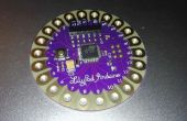
/*++ Sheep - Use a combination of RGB and IR LEDs and a photosensor to imitate crowd-reactive (emergent) behavior This code goes with the Fuse Factory Workshop "Make an Emergent Behavior Sculpture With The Arduino" http://thefusefactory.org/2009/09/03/make-an-emergent-behavior-sculpture-with-the-arduino/ The scultpture, or "sheep", is an artistic assemblage of a Lilypad Pro kit (Lilypad base attached to a Lilipad 5V power unit) with a tri-color LED mounted over the 328V MCU on the Lilypad board. A Large Lilypad Protoboard sits between the PSU and the Lilypad itself to route power and to hold resistors and the IR components. The illusion of a quadraped is completed by 1W and 2W LEDs soldered to the PSU "body" and bent as legs. The code depends on a persistent variable called "mood" - when it is zero or near zero, the sheep is "happy". Below zero and the sheep is "lonely"; above zero and the sheep feels crowded or agitated. Loneliness is represented by blue, happiness by green, and agitation by red. In between expressing "mood" (using PWM to shade the RGB LED), the main part of the code checks for IR pulses from other sheep and may emit its own pulses to "call out" to other sheep. By tweaking internal variables, the sheep can be more or less sensitive to the calls of other sheep. The emergent behavior comes out when multiple sheep are assembled and placed on a table, calling out to each other. The flurry of IR pulses can induce the sheep to be happy or perhaps agitated. Few pulses and the sheep exhibits loneliness. Sheep.pde - turn an Arduino into an emergent behavior sculpture Copyright (C) 2009, Ethan Dicks This program is free software: you can redistribute it and/or modify it under the terms of the GNU General Public License as published by the Free Software Foundation, either version 3 of the License, or (at your option) any later version. This program is distributed in the hope that it will be useful, but WITHOUT ANY WARRANTY; without even the implied warranty of MERCHANTABILITY or FITNESS FOR A PARTICULAR PURPOSE. See the GNU General Public License for more details. You should have received a copy of the GNU General Public License along with this program. If not, see .--*//*++ Variable initialization - before the code start, put all of the user-adjustable parameters at the top so they are easy to tweak. --*/// Definitions of "mood" values #define MOODMAX 80 #define MOODMIN (-1 * MOODMAX) #define LONELY (MOODMIN) #define HAPPY (0) #define CROWDED (MOODMAX) #define MSTEPS 5 #define BLEAT_VOLUME 1 // Global definitions of pin assigments (to simplify individual function calls) int statusPin = 13; // onboard status LED is connected to digital pin 13int redPin = 11; // R petal on RGB LED module connected to digital pin 11int greenPin = 9; // G petal on RGB LED module connected to digital pin 9int bluePin = 10; // B petal on RGB LED module connected to digital pin 10int sensorPin = 5; // IR phototransistor connected to digital pin 5int irPin = 6; // IR LED connected to digital pin 6// Start off expecting to be happy int mood = HAPPY; // Keep track of the sense of the input pinint eye = 0; // And remember how "loud" we are "bleating" (flashing our IR LED)int bleat = BLEAT_VOLUME; /*++ setup() - The Arduino environment will call the code in setup() one time only, right after the board is reset. Put code in this function to initialize I/O pins and such - things that only need to be done once during a run. --*/voidsetup() { // for debugging Serial.begin(9600); Serial.println("Sheep v0.02"); // Mostly, our I/O pins are outputs to LEDs pinMode(statusPin, OUTPUT); // sets the statusPin to be an output pinMode(redPin, OUTPUT); // sets the redPin to be an output pinMode(greenPin, OUTPUT); // sets the greenPin to be an output pinMode(bluePin, OUTPUT); // sets the bluePin to be an output pinMode(irPin, OUTPUT); // sets the irPin to be an output // One exception is the IR phototransistor pinMode(sensorPin, INPUT); // sets the sensorPin to be an input Serial.print("Setting IR 'bleat' to "); Serial.println(bleat); analogWrite(irPin, bleat); } /*++ loop() - the Arduino environment will call the code in this loop forever. Put interesting things in here that are meant to run endlessly after setup() is called once. The only way out of this loop is to reset the board. --*/voidloop() // run over and over again { // Set our RGB LED to reflect our "mood", which will hopefully change from time to time set_mood(mood); // Slow down how fast we react to other 'sheep' delay(100); // delay for .1 second // sensorPin has a 10K pullup resistor, so *no* light reports a 1. We need to // invert the logical sense of the pin if we want to think of the light logically // as 1-is-on/0-is-off eye = 1 - digitalRead(sensorPin); // set eye to 1 if we "see" any IR light // Report our present status everytime through the loop Serial.print("Mood is "); Serial.print(mood); Serial.print(". Sensor is "); Serial.println(eye); // If we see pulses from another 'sheep', increment the mood, but not past MOODMAX if (eye) { // since humans cannot "see" infrared light, use the status LED as a visible indicator digitalWrite(statusPin, HIGH); // echo IR input detection on the status LED mood += MSTEPS * 2; if (mood >MOODMAX) { mood = MOODMAX; } } // If we don't see any IR pulses, decrement the mood, but not below MOODMIN else { // since humans cannot "see" infrared light, use the status LED as a visible indicator digitalWrite(statusPin, LOW); // echo IR input detection on the status LED mood -= 1; if (mood < MOODMIN) { mood = MOODMIN; } } } /*++ set_mood - convert "mood" to a color scheme Mood varies from some negative number to that same value as a positive number (so far, -80/+80 and -100/+100 produce reasonable results). Proportionally, the continuum of mood to color mapping resembles the following: Mood -100 0 +100 Lonely -> Happy -> CrowdedR 0 0 0 30 100G 0 30 100 70 0B 100 70 0 0 0--*/void set_mood (int mood) { // Start out with each color being off - adjust upwards based on "mood" unsignedchar redness = 0; unsignedchar greenness = 0; unsignedchar blueness = 0; #ifdef DEBUG Serial.print("Mood is "); Serial.println(mood); #endif // blueness is all about mood being less then happy if (mood < HAPPY) { blueness = abs(mood); greenness = MOODMAX + mood; } // redness is all about mood being more than happy elseif (mood > HAPPY) { redness = mood; greenness = MOODMAX - mood; } // greenness is about mood being around happy else { greenness = MOODMAX; } // Set the LED to reflect our present mood color(redness, greenness, blueness); } /*++ color(r, g, b) - set the tri-color LED to the requested color value Uses analogWrite(pin, value) to set PWM value for each individual LED color The Tri-color LED is a common-anode device, so to make light, we ground the desired pin. To invert the PWM waveform, we subtract our desired intensity from 255, so that, for example, if we want red off, logically, we pass around a value of zero, but set the PWM value to 255 so that the pin is driven high 100% of the time. To get red to the maximum brightness, we pass around a logical value of 255, but set the PWM value to 0, pulling that pin low 100% of the time.--*/void color (unsignedchar red, unsignedchar green, unsignedchar blue) // the color generating function { #ifdef DEBUG Serial.print("color("); Serial.print(red,HEX); Serial.print(blue,HEX); Serial.print(green,HEX); Serial.println(")"); #endif // invert the sense of the PWM value when calling analogWrite() for each color analogWrite(redPin, 255-red); analogWrite(bluePin, 255-blue); analogWrite(greenPin, 255-green); }

